
New vs. Used SawStop
Table saws have long been considered the most dangerous power tool, sending more than 30,000 people to the hospital each year in the United States.
Before SawStop shares its patent with the public, we thought we’d see how much of the brake’s engineering we could uncover with industrial X-ray CT. Using our Neptune scanner and Voyager software, we compared CT scans of a new and deployed brake to understand how the SawStop works and the hit it takes when one of them comes to the rescue.
How does SawStop work?
The SawStop safety brake represents a remarkable engineering feat in woodworking safety. It operates by running an electrical current through the saw blade, which is continuously monitored by the brake cartridge. When the blade comes into contact with skin, the electrical signal is disrupted, triggering the brake mechanism. In less than 5 milliseconds—faster than a car airbag—the actuator assembly unleashes the aluminum pawl and halts the blade spinning at 3,500 RPM. The saw blade teeth bite into it, and the blade’s momentum causes it to retract under the table to prevent further injury.
Take the 3D reconstruction of the new SawStop for a spin in the Voyager window below. You can toggle between 3D and 2D views by clicking the 3D ▼ button in the upper right corner of the window. From there, you can scrub through the X, Y, and Z axes of the SawStop. Click Explore the Scan to open the full project for yourself.
SawStop Components
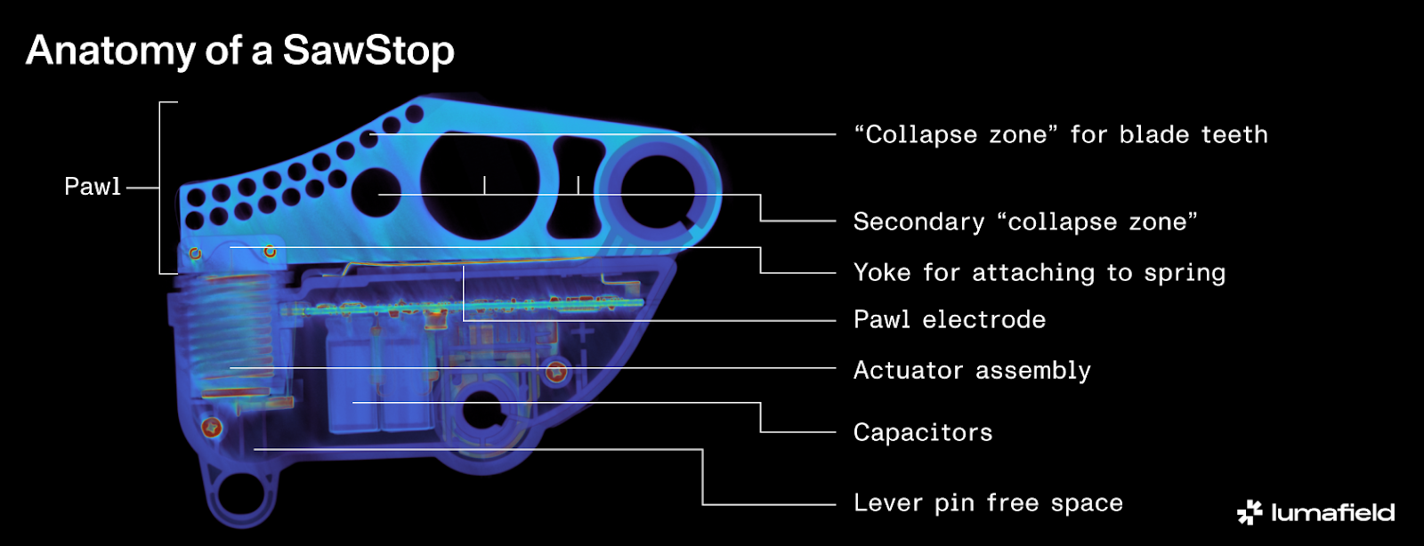
Actuator Assembly
- The actuator assembly features a robust spring mechanism responsible for deploying the pawl into the blade.
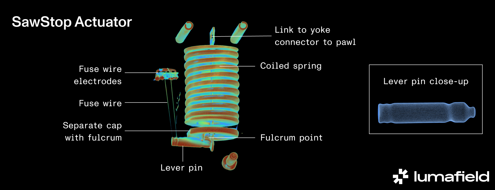
- A thin fuse wire, typically made from Nickel chromium or hardened steel, is a critical component that melts to release the lever pin, allowing the spring to push the pawl into the blade. Material selection is crucial; the fuse wire needs to have a high tensile strength and a high Young’s Modulus, indicating rigidity and stiffness.
- Voyager’s radial measurement tool shows the fuse wire’s diameter to be less than 0.4 mm. This small but mighty wire can withstand the 150 lb-force spring thanks to a clever 3:1 mechanical advantage based on its distance from the fulcrum point. This ensures the wire only needs 50 lb-force of tensile strength, making it both strong and easily fusible.
- The fuse wire is designed to be stable enough to resist stretching or thinning over time despite the intense repeated vibrations from the saw use, ensuring it doesn’t prematurely release the spring.
- The current travels between these two electrodes on the top of the PCB, a distance along the wire of less than 1.5 mm.
- The lever pin has ridges designed to hold the fuse wire in place and prevent it from slipping with vibrations. It’s small enough to ensure it doesn’t get stuck on the pawl link when released, which could potentially prevent the spring from firing.
Controller
- The brake system is managed by a sophisticated Digital Signal Processor (DSP) embedded in the PCB, providing the necessary computing power to monitor and control the brake’s components.
- The chip monitors the signal over the gap between the brake and the blade, distinguishing the change in signal caused by a finger touch from other noise sources like intense vibrations, heat build up, wet wood or nails in the wood. The chip ensures the entire system can deploy in time to prevent serious injury.
Pawl
- The aluminum pawl is engineered to be soft enough for the saw blade teeth to bite into but strong enough to stop the blade.
- The pawl includes strategically-designed primary and secondary “collapse zones” with weight-reducing holes for faster deployment.
- The pawl’s rotation point is designed for free movement, with intentional gaps in the plastic housing that allow the plastic ring to expand or contract, preventing thermal expansion or sawdust build-up from binding the pawl and interfering with release.
Locking pin
- The locking pin uses a cam action to secure the brake to the saw trunnion, ensuring proper installation and continuous contact through vibrations.
- The pin’s design includes a bent tab to maintain contact without damaging the PCB during operation.
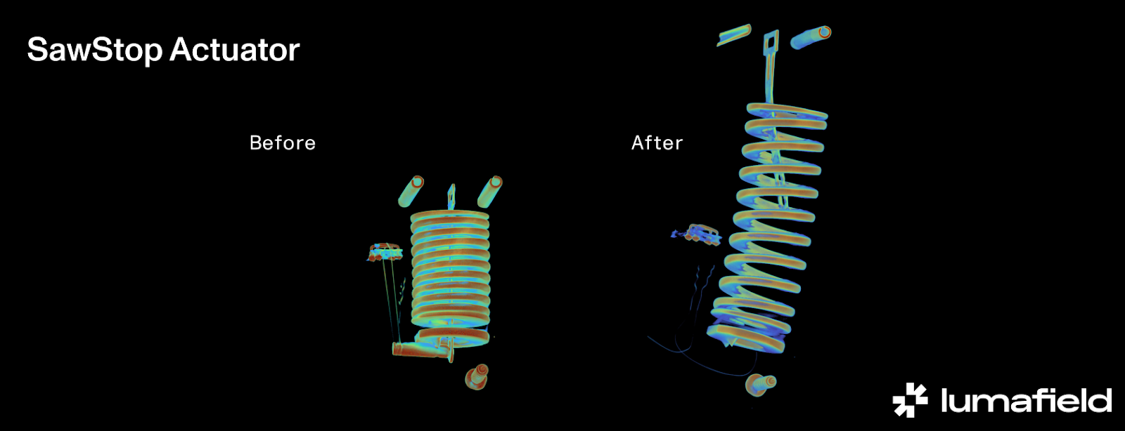
New vs. Used SawStop
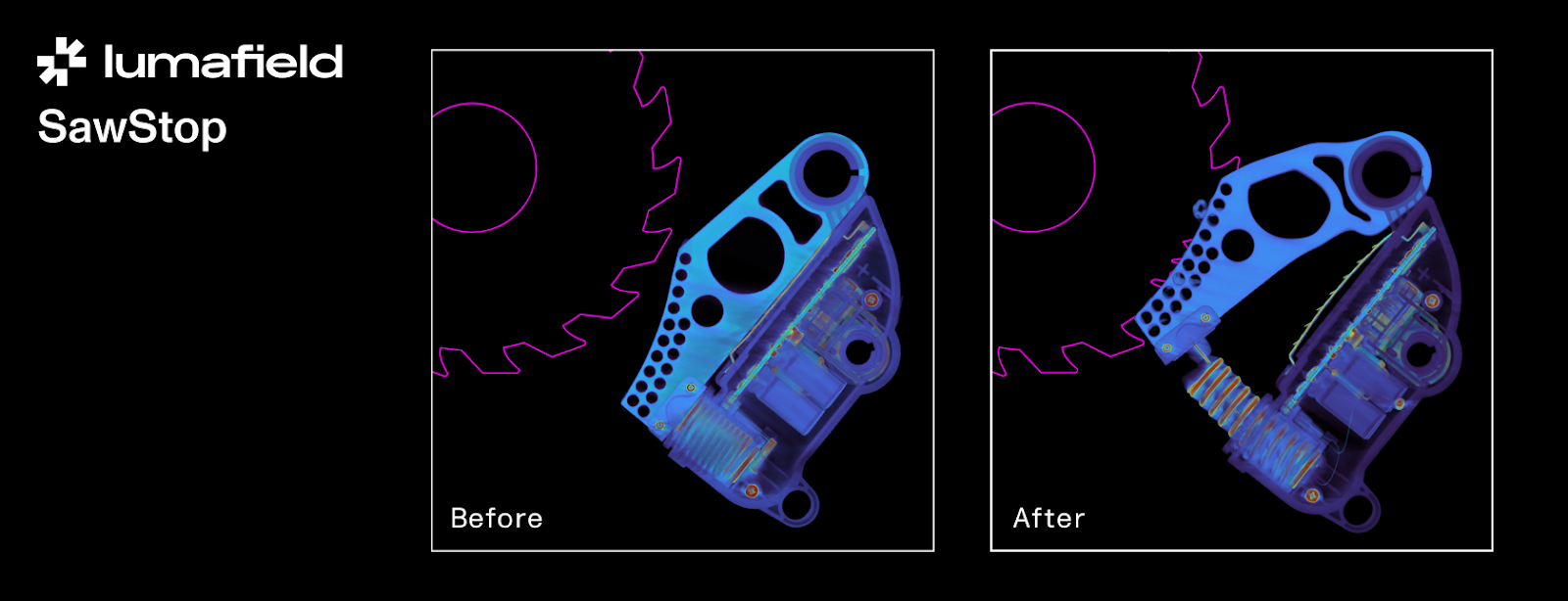
In our scan of the used brake, we can see the blade’s exact path into the pawl. It only took two teeth for the primary collapse zone to catch and effectively stop the blade in its tracks. The secondary collapse zone has also clearly functioned as-designed.
We see that in place of the taught fuse wire of before, the thin thread is broken, evidence that completion of the electrical circuit triggered the brake mechanism. The thrown locking pin is also visible, highlighting the mechanical release that allows the spring mechanism to drive the aluminum pawl into the blade.
What’s next for SawStop?
The stark reality of table saw injuries has led the U.S. Consumer Product Safety Commission (CPSC) to consider mandating advanced safety features, such as the SawStop safety brake, on all new saws sold in the country.
SawStop was founded in 1999 by Dr. Steve Gass, a patent attorney and physicist who invented the Active Injury Mitigation (AIM) system to halt a saw blade almost instantly upon contact with skin. Initially, Gass attempted to license the technology to major power tool companies, but none were interested. Now, opponents of the CPSC’s proposed law claim that implementing the technology would raise the price of table saws. Despite previous litigation against would-be imitators of their safety brake, SawStop has committed to dedicating its original patent to the public when these new regulations go into effect.
With Neptune and Voyager, we see how SawStop’s technology exemplifies the kind of precision engineering that can prevent serious injuries and even save lives. Industrial CT not only provides the best tool for exploring the complexities of electromechanical systems like these, it also offers manufacturers the insights they need to push the boundaries of safety innovation.


.png)


.png)
.png)